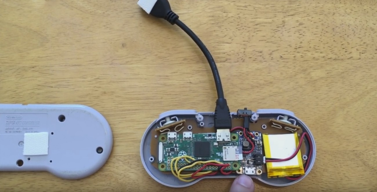
- #Diy snes controller to usb update#
- #Diy snes controller to usb code#
- #Diy snes controller to usb Pc#
- #Diy snes controller to usb download#
r/DIY should not be your first stop for your question.Īll help request must go in "self posts" or the stickied thread at the top of the subreddit. Please consider adding photos and doing some basic research into your question. If you are posting a help request, please include as many details as possible. Read our guidelines before posting New to reddit? Click here! Tips: The subreddit got a facelift! Check out the information here! r/DIY now has a Discord channel! Come chat with us!ĭid you miss the AMA with Patrick DiJusto? Click here to read it!

AMA with Travis Larson is over Check it out!.COVID-19 DIY PPE Post is live, connecting medical professionals with DIYers!.Quinn Dunki of Blondihacks answers your questions! Read her insights into machining and cat dentistry here.Joystick.begin(false) //Initialise the controllersĭigitalWrite(latch, HIGH) //latch pulse, lock the state of the buttons in the registerīuttons1 = 0 //zero the variables to receive new values.īuttons1 |= (digitalRead(data1) << 0) //first bit read before clock. Uint16_t buttons1 = 0, buttons2 = 0 //the variables for each controller stateĬonst bool testAutoSendMode = false //we choose when to send the values over USB Int clk = 4, data1 = 7, data2 = 6, latch = 5 //two data lines, one for each controller.
#Diy snes controller to usb code#
If you already installed the library and connected everything, just burn the code bellow in the Arduino and you have finished. More information can be found in this useful document.
#Diy snes controller to usb Pc#
Then you can code the board to receive the button states from the controllers and send them to the PC as a USB HID controller. With this library, you can make the Arduino appear in the computer as up to 3 controllers.
#Diy snes controller to usb download#
Just download it and extract in the libraries folder of the Arduino IDE files. The library I found works great, it was coded by Matthew Heironimus, and can be found here.
#Diy snes controller to usb update#
If you don’t have the version 1.6.6, please update so we can continue. Ops, I assume that you have the last version of Arduino software, because the library does not work with version 1.6.5 or below. In addition, I wanted to complete the project in one afternoon. I still don’t know much about the USB protocol and its way of communication. A reading in the code can clear this better. Note: Every line is shared between the controllers except the data line, this means that latch, clock, 5v and GNd are connected in the controllers connected, the data lines must be separated, I used the pin D6 for the data line of the second controller. I connected as follows, but you can change in the code if you want. The SNES controller connector pinout is : In my defense, I used the worst soldering iron ever. You can see the details below: I used two male pin from headers to make the connector. For this I used some veroboard and male headers basically.Please, remember that only the Arduino micro and Leonardo can be used for this. I had to connect the controllers to the Arduino.

The models Micro and Leonardo have a USB port in the ATmega used (32u4), and only one chip is used for USB communication and general coding. Usually the user may not even realize that the board has two processors. Note: The other Arduino models generally use another ATmega to handle the USB protocol, while the main chip is used for code. The Arduino Leonardo is probably suitable for this too, as it also has a native USB port. The thing about the Arduino Micro, is that like the Arduino Leonardo, it has native USB, being able to act like a keyboard, a mouse, a joystick, or whatever. However, I had a Arduino Micro and some veroboard. I wanted to play Super Mario, but I did not have this adapter anymore. I found the USB implementation to hard to understand, so I just followed the instructions. Some time ago, I built a adapter for connecting SNES controllers to PC from Raphaël Assénat’s site using a ATmega 8 with the VUSB library.

I don’t think I play bad using the keyboard, but I prefer using controllers, even better if the controllers are the ones of the console emulated. I have played in emulators since always, a lot of them, including the SNES. I had the Megadrive, but played some lot in Super Nintendo too. Super Nintendo, together with the Sega Megadrive (or Genesis) are the representative consoles of the 16-bit era.


 0 kommentar(er)
